
XB-650i Design Evolution
8 Years in the making...
Lucas and Warren 1st started talking about a new, bigger tool in 2017, after exhibiting at a Tire Service specific trade show put on by Tech International. We had been looking for new opportunities to develop a new model, and while we were aware of hydraulic bead breakers, we never really had a chance to see them in person until that show. It seemed like an obvious progression of the BeadBuster product line, and after studying the hydraulic tool design it looked like there were alot of areas of improvement that we could offer with a screw-driven version of a large bead breaker. These are the 1st sketches Lucas made of concepts in Oct 2017.
Concept 1 - similar to the XB-550 and Pneu-Tek tools
Concept 2 - clamping achieved by straps that are moved by a screw, similar to a hydraulic tool
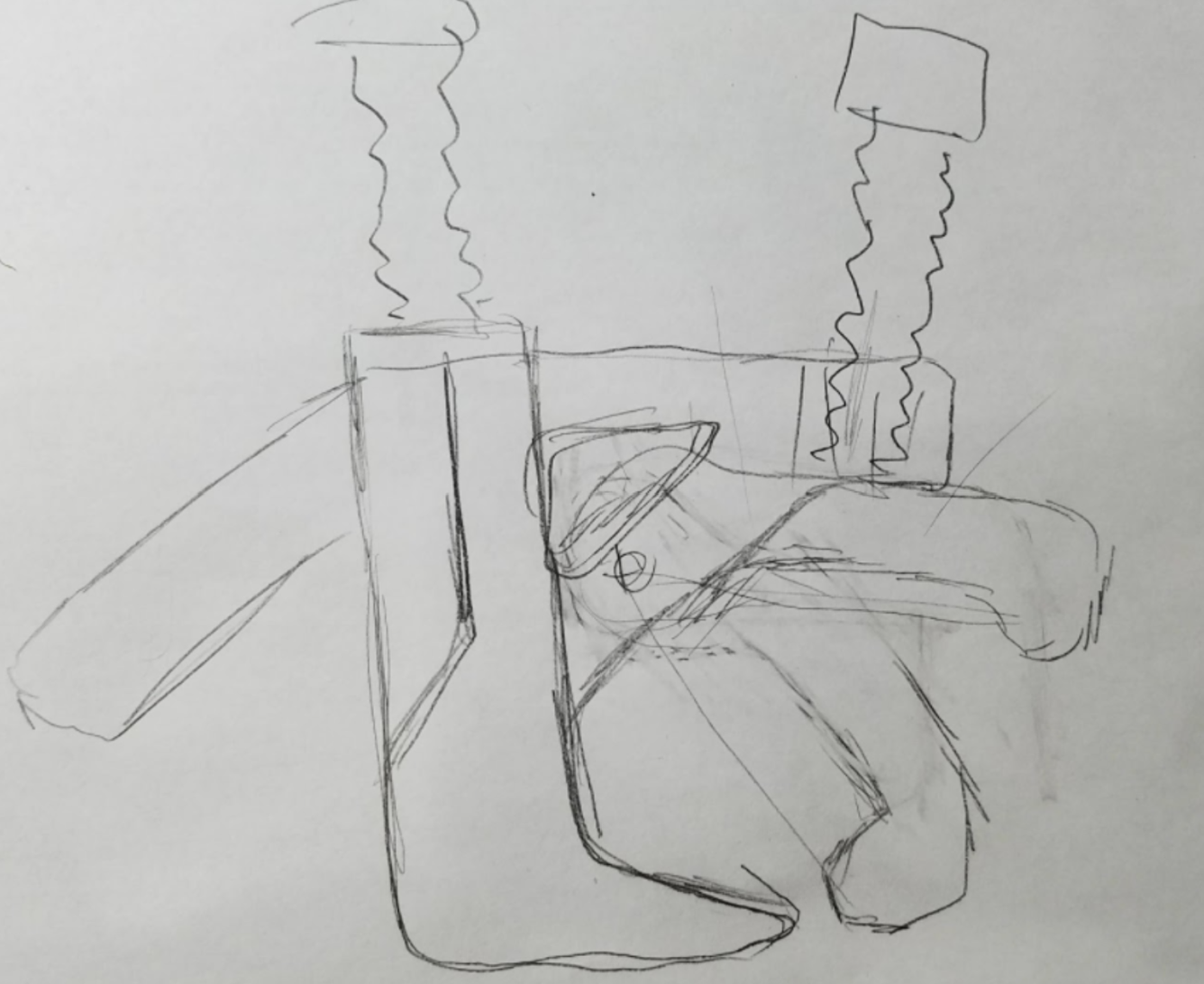
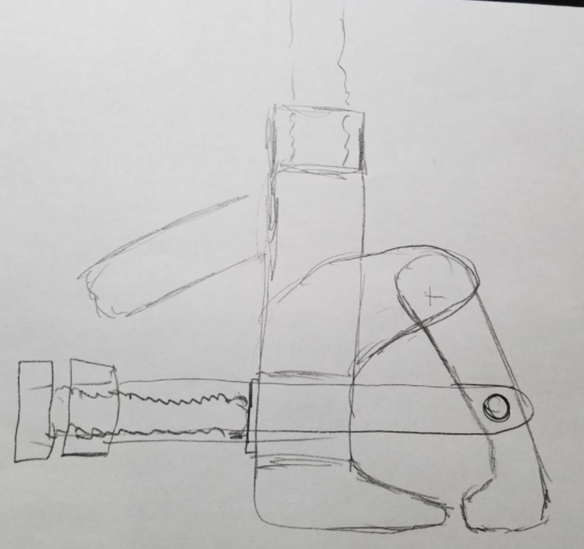
It became obvious pretty quickly that we had to move the clamp screw away from the clamp arm to improve access to it, while still maintaining perpendicular force to the clamping surface. Taking the clamp straps from the hydraulic tool form factor, and integrating that into a screw driven architecture was the crux of the design progression from this point on.
MARK I CAD Model
At the time we were still making the XB-450 and XB-550 as welded assemblies. These 1st couple CAD designs all used a similar construction method: welded tubes and laser cut plate parts. This version uses a moving ram screw exactly like how the 450 and 550 tools work. In order to get a competitive amount of stroke (4"+) the height of the tool in the retracted position becomes unwieldy...although this is the simplest way to construct the tool. Similarly, the clamp screw would move in-and-out a carrier nut attached to the clamp straps, and the tip of the screw would ride against the tool body.
MARK II CAD Model
The change here is fixing the ram screw, and retaining it somehow from the inside of the tool body, and the female thread or nut becomes integrated with the ram foot, so that turning the screw articulates the ram foot. This is how the Pneu-Tek tool is designed. The method of ram screw retention was not really worked out yet, but this made a much better form factor for the tool and we knew it was the direction we needed to head.
MARK III CAD Model
At all points along the design evolution process we were looking for ways to optimize for weight, as that is one of the biggest drawbacks of a hydraulic tool: 30-40 lbs is alot to lug around when you are working under a loader on the back side of a wheel.
This was an attempt to take weight and complexity out of the clamp mechanism...why do we need a hinge at all?
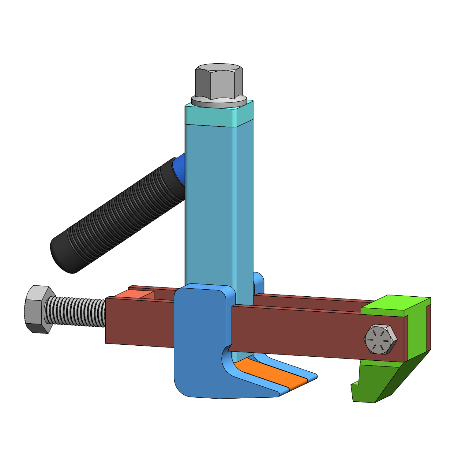
MARK IV CAD Model
Another major complaint of hydraulic bead breakers is insufficient clamping force. Often the operator can not get the tool fully mounted before the ram action would initiate. So we were thinking about maximizing clamping force, and this mechanism is an over-center linkage that quite literally produces infinite clamping force at the end of the stroke. It also placed the clamp and ram screws next to each other which was thought to be an ergonomic advantage while being used.
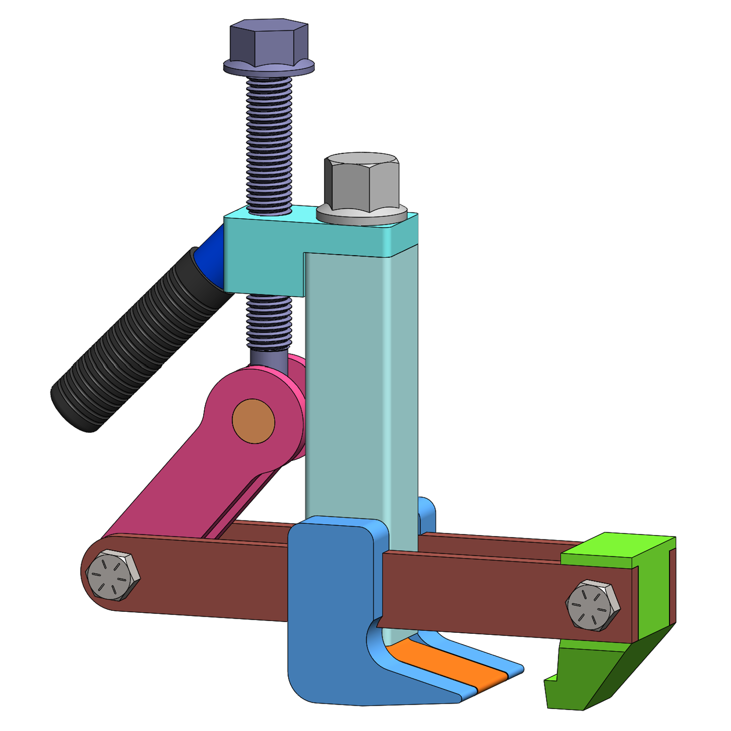
MARK V CAD Model
We realized that the hinge-less clamp arm was a bad idea, and there would be too much bending moment on the clamp straps, especially at theoretically infinite clamping force from the over-center mechanism! So this version reverted back to a hinged clamp arm while keeping the over-center mechanism.
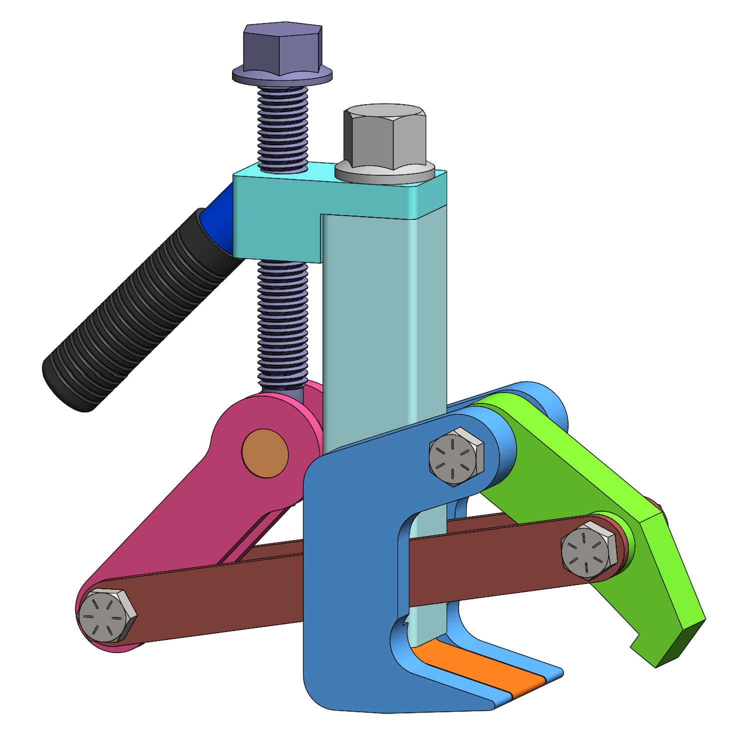
MARK VI CAD Model
This was a refinement of the last design, including stabilized clamp straps, roller bearing elements on the clamp carrier, and a bit more thought on how it would be constructed and built. Looking back on this design it looks like a finger-cutting mess, but at the time I really thought this was where we would end up with the final design. We even 3D printed a full size version in plastic, that I keep on display in the production line.
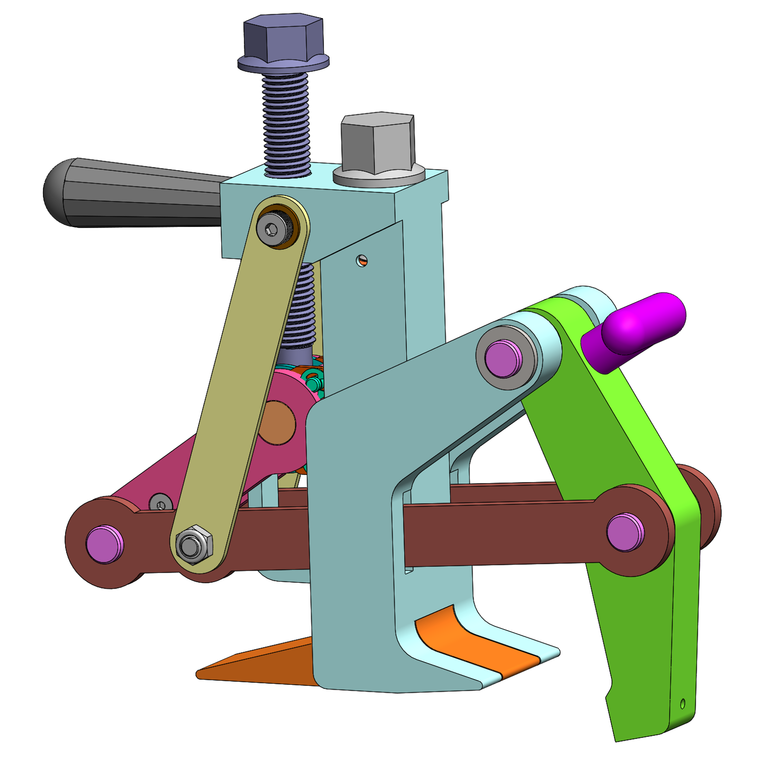
MARK VII CAD Model
This revision to the design happened around 2024, when we discovered investment casting and switched the XB-450i and XB-550i HD to investment cast bodies. The last version was an unwieldy and complicated design that I had doubts that we could actually manufacture for a reasonable cost with required quality. Switching to casting completely changed that outlook, as I could make the design pretty much however I wanted. And it also enabled me to really start looking at optimizing for weight, and start nipping and tucking at superfluous steel. For instance, the vastly smaller clamp hinge design in this concept, because it can be cast, would save several pounds alone. Also, integrating a handle grip into the casting that would act double-duty as a structural brace was now possible.
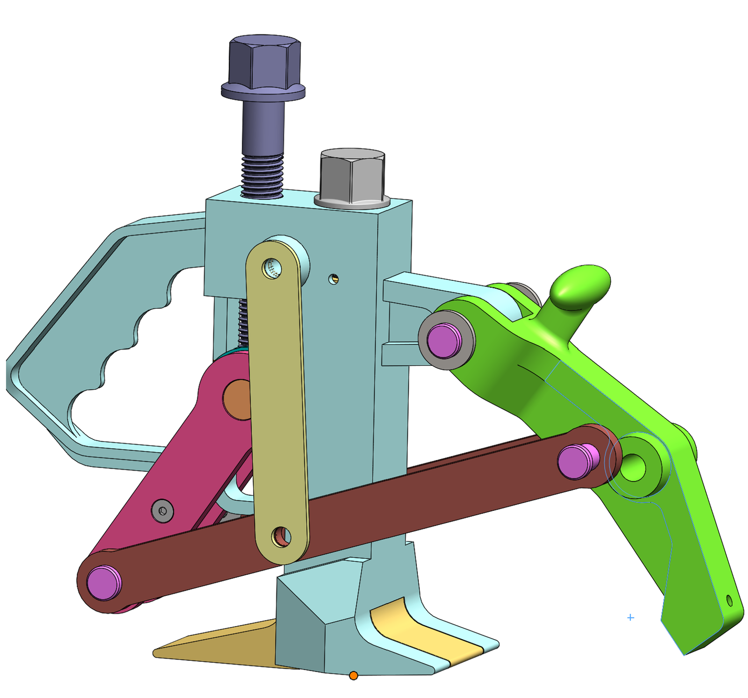
MARK VIII CAD Model
This iteration happened as a result of abandoning the over-center mechanism. I realized the reason hydraulic tools' insufficient clamp force was not because the cylinders don't make enough force; its because of the pressure valve switch that automatically changes over to ram mode after a certain pressure is achieved. This is what makes a hydraulic tool have automatic operation, but its also a fatal flaw because in many cases it switches over too soon before the tool is fully clamped. I reverse engineered the pressure valve and calculated that the hydraulic clamps are maxing out at approximately 1.5 tons. An over-center mechanism isn't remotely needed to make more clamp force than a hydraulic tool, that can be easily achived with a sufficiently beefy screw.
So this version of the design introduced a captured clamp screw in the clamping direction, and a moving clamp carrier. I also experimented with tension rods rather than clamp straps. We are starting to converge on the ultimate design with this version.
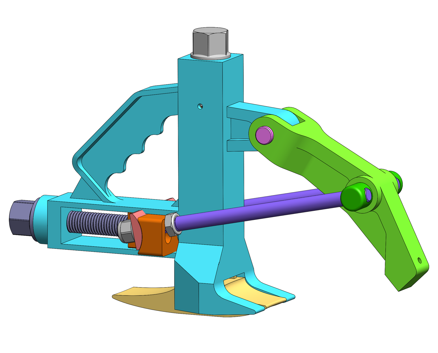
MARK IX CAD Model
Here we have improvements to the ergonomic handle, and I reverted back to the clamp straps, which would be far less complicated to inegrate than tension rods, but still be very strong and economical if cut from plate.
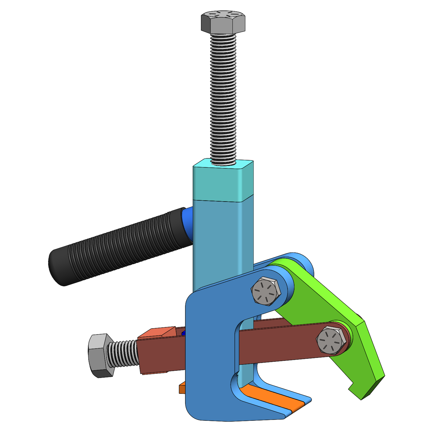
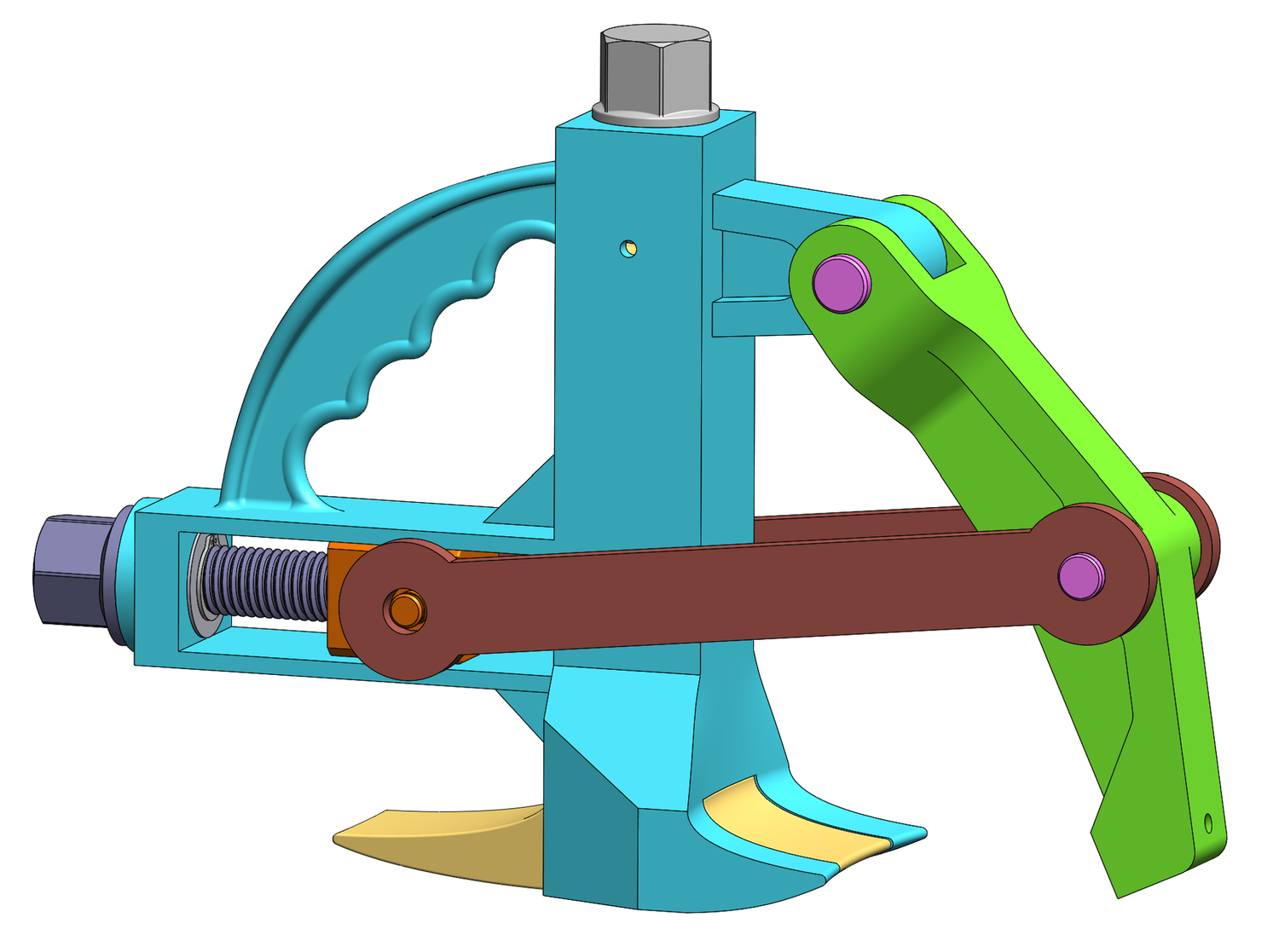
MARK X CAD Model
This version is very close to the finished design. The clamp straps are optimized for strength and weight. The clamp arm hinge has been fully optimized as well, introducing hinge pockets that act as a hinge journal, eliminating the need for a heavy, overly large hinge pin.
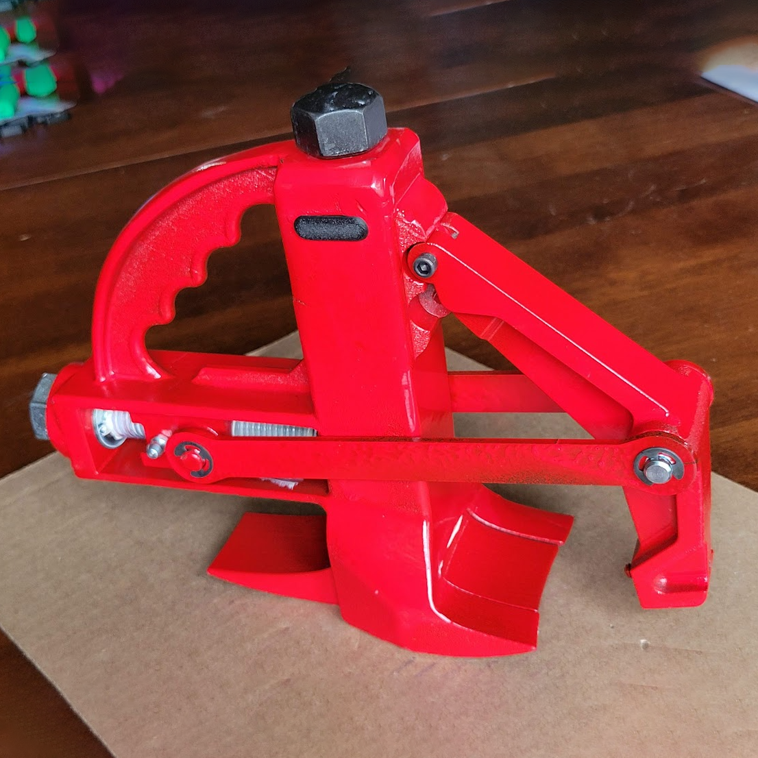
MARK X Prototype
In August 2024 we made a functional prototype of the Mark X design using 3D metal printing for all of the cast parts. We sent this into the field to be used and abused by technicians, to learn what does and doesn't work about the design.
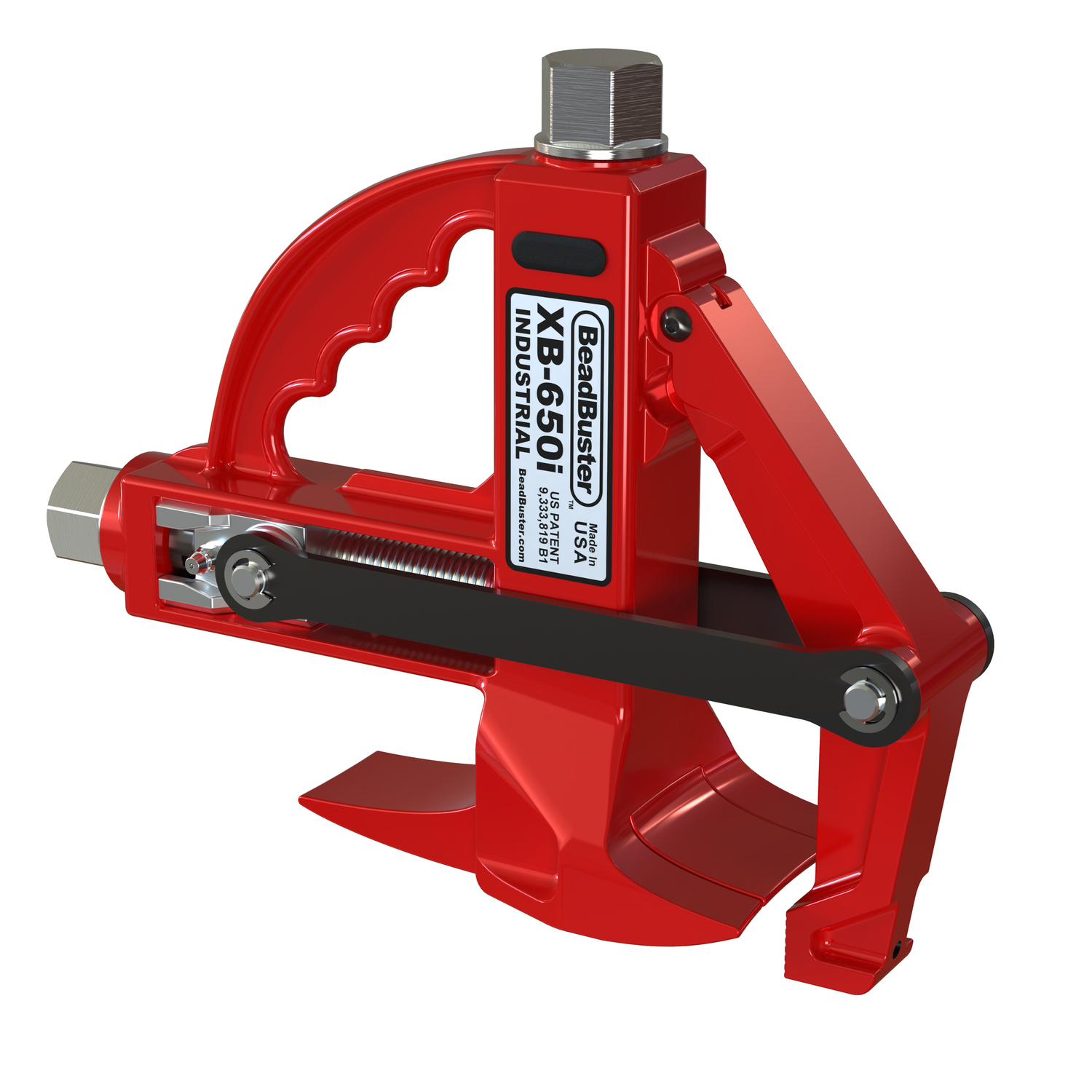
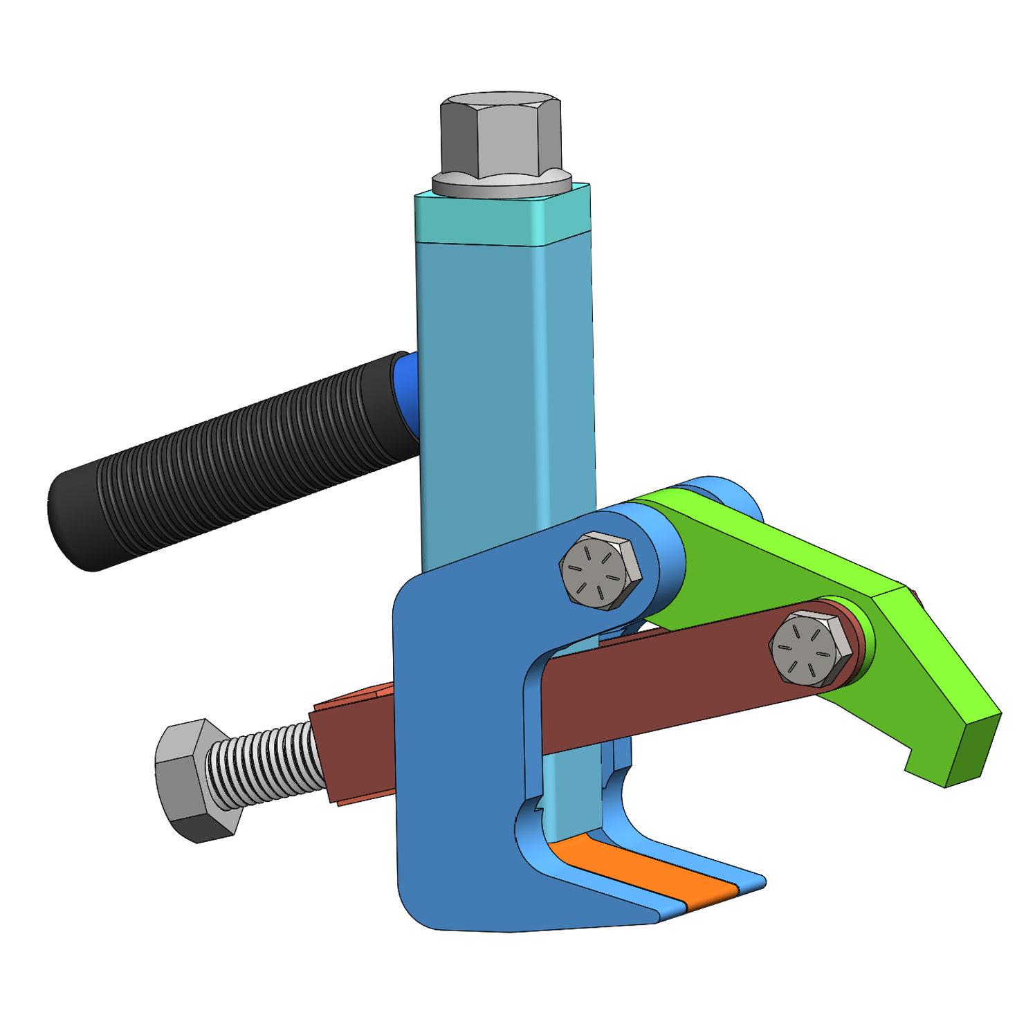
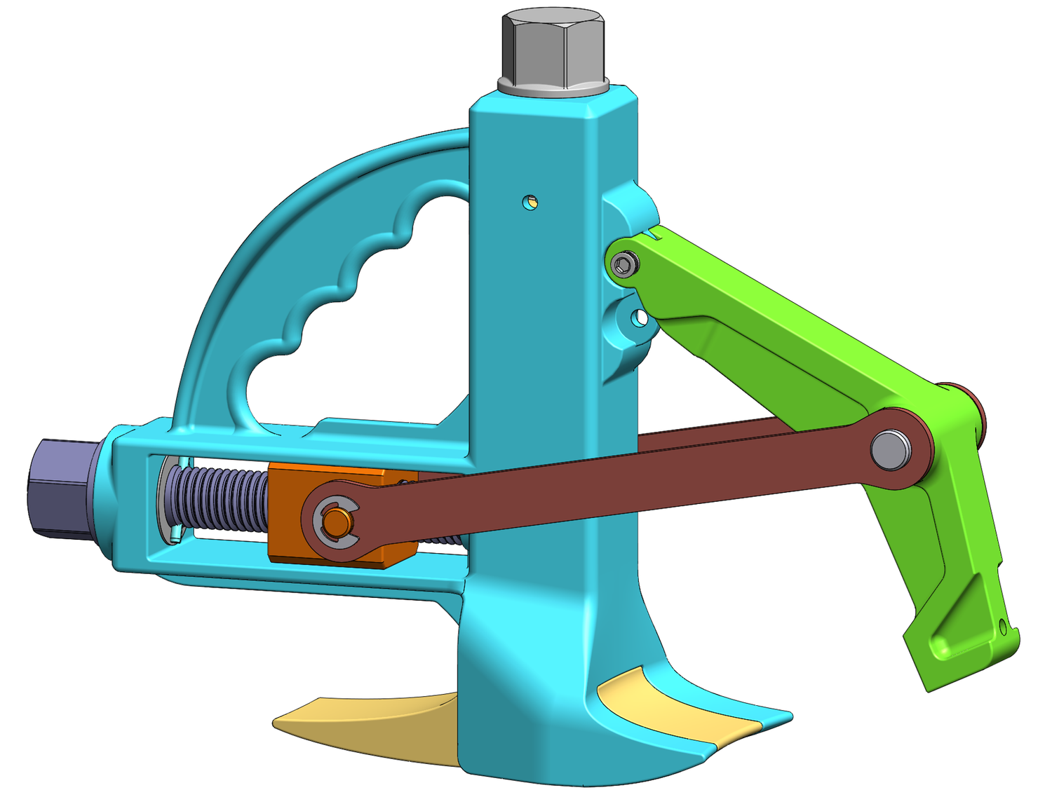
FINAL XB-650i Design
After some valuable learning from the field trials, we made some improvements including:
- A floating ram nut to prevent side loading and binding n the ram screw
- Clamp and Ram threads converted to ACME for strength and reliability
- Improved ram and clamp screw retention features
- Inclusion of oil impregnated thrust bearings on both the clamp and ram screw
- Longer clamp arm
>> Learn more about the BeadBuster XB-650i Innovative Features
As this writing in May 2026, this is the final design that we are launching with initial production of the XB-650i